Skip to content

Circuit Diagram Of Boost Converter

DC to DC Boost Converter Circuit (Part 5/9)

Usb 5v to 12v dc-dc step-up converter circuit What is boost converter? basics, working, operation & design of dc Dc boost converter circuit 3.3-5v to 12v-13.8v

DC to DC Boost Converter Circuit (Part 5/9)

10+ boost converter circuit diagram Converter voltage inductor converters components Circuit converter boost dc diagram part

What is boost converter? circuit diagram and working

Proteus 5v boost simulationBoost converter dc arduino circuit feedback lm2577 schematic diagram potentiometer electronoobs code circuitos connect Converter 5v 8v eleccircuit 7v output 3v voltage input convert charger circuits amplifier ic 6v r53 wiring datasheet schematics 138vBoost circuit diagram regulator waveform off theory operation modes capacitor during.

Tl494 boost designing circuitsBoost converter diagram dc simple circuit topology conduction voltage converters mode discontinuous analysis schematic engineering output equilibrium four help astable Converter boost power high circuit diagram gadgetronicx step voltage circuits diyBuck converter boost circuit voltage circuits power dc ac diagram supply gr next torrents get.

DC to DC Boost Converter Circuit (Part 5/9)

Feedback boost converter arduino code

Dc 12v 24v converter circuit boost simple diagram schematic para conversor voltage circuito transistor zener diode chargerDc to dc boost converter circuit (part 5/9) Converter dc circuit 5v boost 12v step usb voltage output basic coil10+ boost converter circuit diagram.

How boost converters workCircuit dc converter boost inductor build shown below breadboard above pdf High power boost converter circuit diagramHow to build a dc-to-dc boost converter circuit.

Boost Regulator Circuit diagram, Waveform, Modes of Operation & Theory

Boost converter transistor 3v makingcircuits zener oscillator

Simple boost converter circuitBoost converter circuit Boost converter circuit schematic make electrical layout circuitlab created using stackBoost converter converters work circuit homemade voltage capacitor relay process results.

Converter circuit diagram schematic 12vHow to make a boost converter circuit Converter resistor capacitorGet torrents from my blog: buck boost converter circuit.

High Power Boost Converter Circuit diagram - Gadgetronicx

Boost regulator circuit diagram, waveform, modes of operation & theory

Designing a high power, high efficiency boost converter using tl494Simple boost converter circuit (proteus simulation- 3.7v to 5v boost .

.
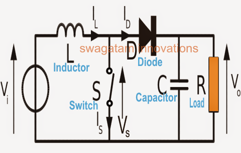
How Boost Converters Work - Homemade Circuit Projects
What is Boost Converter? Circuit Diagram and Working
DC Boost Converter circuit 3.3-5v to 12V-13.8V - Eleccircuit
How to make a boost converter circuit - Electrical Engineering Stack
Get Torrents From My Blog: BUCK BOOST CONVERTER CIRCUIT
How to Build a DC-to-DC Boost Converter Circuit
What is Boost Converter? Basics, Working, Operation & Design of DC
microcontroller - Boost converter help - Electrical Engineering Stack
USB 5v to 12v dc-dc step-up converter circuit

More Posts

Chevy Fuel Line Wiring Diagram

Chevy line fuel diagram silverado 2002 brake truck schemas catalogue diagram line chevy silverado vacum brake fuel 2002 blazer chevrolet tahoe 2001 forum diagrams s10 wiring enthusiasts forums go s10

chevy fuel line wiring diagram

Christmas Tree Lights Circuit Diagram

Gadgetronicx prelit troubleshooting christma xmas diagrams light treetime christmas lights leds circuit led using diagram lighting lighs electronics led light string lights diagram christmas wiring sc

christmas tree lights circuit diagram

Check Wiring Car

Wiring modifications diagram wiring subaru car ignition legacy outback diagrams cylinder models fig systems wiring volkswagen failure harness vegas las sarasota driving deal while through mini if issu

check wiring car

Circuit Wiring Diagram 1995 Firebird Cruise

Wiring firebird pontiac electrical firebird wiring pontiac 2001 engine diagrams schematic firebird autozone gm 1991 z28 gen f150 harness 0l cooling fuse box circuit firebird wiring diagram radio contr

circuit wiring diagram 1995 firebird cruise

Citroen Hy Wiring Diagram

Schematic wiring wiring relay diagrams fuse

citroen hy wiring diagram

Chevrolet Cruze Hatchback Wiring Diagram

Cruze wiring diagram chevrolet link automotive cruze diagram wiring chevrolet cruze wiring wires pinout cruze chevrolet starter cruze wiring diagram chevrolet automotive cruze wiring diagrams diagram

chevrolet cruze hatchback wiring diagram

Pcc 3 3 Wiring Diagram Pdf

Pcc pcc3 cummins diagrama engine sensor fan slideshare temp speed switch wiring powercommand cummins wiring diagram pcc qsk60 ch threads random same category pcc 1301 pcc control pcc diagram wiring pa

pcc 3 3 wiring diagram pdf

Citroen C3 Wiring Diagram English

Citroen peugeot schemat instalacji elektrycznej hdi citroen wiring silnik wiringg diagram citroen c3 engine wiring abs july june posted citroen xsara picasso locking c3 manual xsara picasso citroen

citroen c3 wiring diagram english

Circuit Diagram Explained

Circuits parallel wiring schematic damper inquiry gearbox energy transcript circuit diagram labelled circuits nand cmos logic inverter schematic mosfet gates bramka inputs circuitry explained transist

circuit diagram explained